
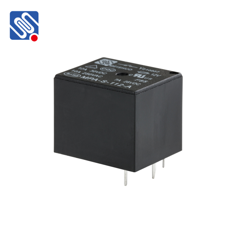
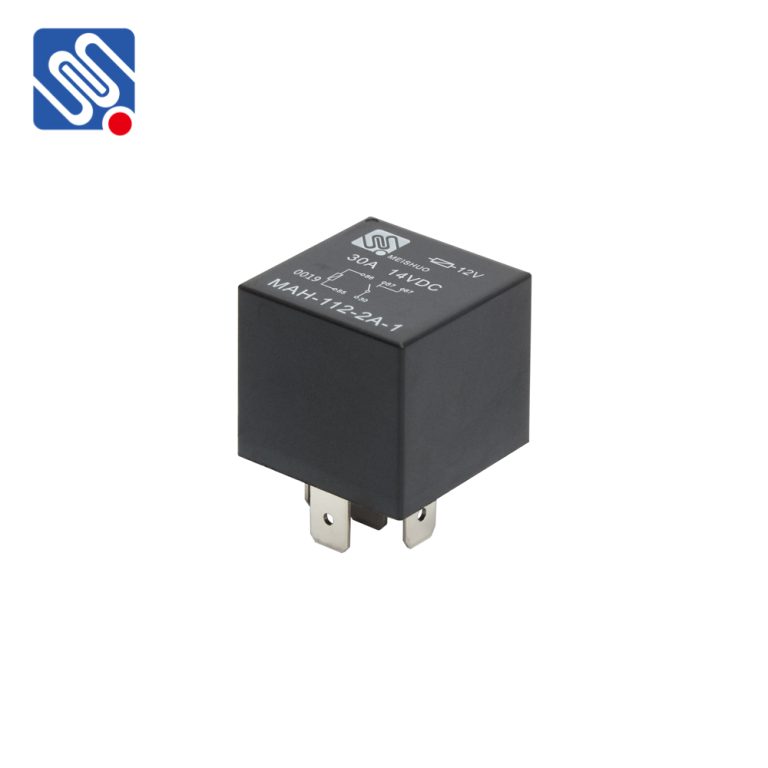


Relays are essential components in various electrical and electronic systems, usually used in automated control circuits. It is an “automatic switch” that uses a small current to control a large current. It plays the role of automatic regulation, safety protection, and circuit conversion in the circuit. Testing a relay is crucial to ensure its proper functioning and to diagnose any potential issues. Here are the steps to test a relay effectively:
1. Visual Inspection
Before beginning any electrical testing, perform a preliminary visual inspection of the relay. Check for any signs of physical damage, such as a cracked or melted casing, burned contacts, or loose wires. If the relay has a transparent cover, look for visible signs of arcing or corrosion on the contacts. Also, check for any discoloration or charring on the relay body, which could indicate overheating.2. Coil Resistance Measurement
- Equipment Needed: A digital multimeter (DMM) set to the resistance (Ω) mode.
- Procedure:
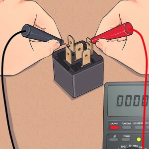
3. Contact Resistance Measurement
- Equipment Needed: A digital multimeter (DMM) set to the resistance (Ω) mode.
- Testing Normally Open (NO) Contacts: With the relay inde-energized state (no voltage applied to the coil), use the DMM to measure the resistance between the common terminal and the normally open terminal of the relay. In a properly functioning relay, the resistance should be very high (ideally infinite). If the measured resistance is low (close to 0 Ω), the normally open contacts may be stuck closed.
- Testing Normally Closed (NC) Contacts: Still with the relay de-energized, measure the resistance between the common terminal and the normally closed terminal. The resistance should be close to 0 Ω. If the measured resistance is high, the normally closed contacts may be dirty, corroded, or not making proper contact.
4. Coil Voltage and Current Testing
- Equipment Needed: A variable power supply, an ammeter, and a voltmeter.
- Procedure:
5. Contact Function Testing
- Testing NO Contacts When Energized: Apply the rated voltage to the coil of the relay. Using the DMM set to resistance mode, measure the resistance between the common terminal and the normally open terminal again. The resistance should now be close to 0 ohms, indicating that the contacts have closed.
- Testing NC Contacts When Energized: With the relay energized, measure the resistance between the common terminal and the normally closed terminal. The resistance should now be very high (ideally infinite), showing that the contacts have opened.
6. Insulation Resistance Testing
- Equipment Needed: A megohmmeter (also known as an insulation tester).
- Procedure: Disconnect the relay from all power sources and circuits. Connect the leads of the megohmmeter to test the insulation between the coil and the contacts, as well as between different sets of contacts. Apply the appropriate test voltage (usually specified in the relay’s datasheet) and measure the insulation resistance. A high insulation resistance value (in the order of megohms) is required for proper operation. If the insulation resistance is low, it could lead to electrical leakage and malfunction of the relay or the connected circuit.