If you’ve ever looked at a relay’s wiring diagram and thought, “What am I even looking at?” trust me, you’re not alone. Relays, despite their small size, play a massive role in modern electrical systems, especially when dealing with heavy-duty applications like 30A loads. But figuring out how to wire one can feel like solving a puzzle. Don’t worry—I’ve got your back.
In this blog, I’ll break down everything you need to know about the wiring diagram (bottom view) of a 30A new relay, so you can wire it up with confidence.
What’s a 30A Relay and Why Does It Matter?
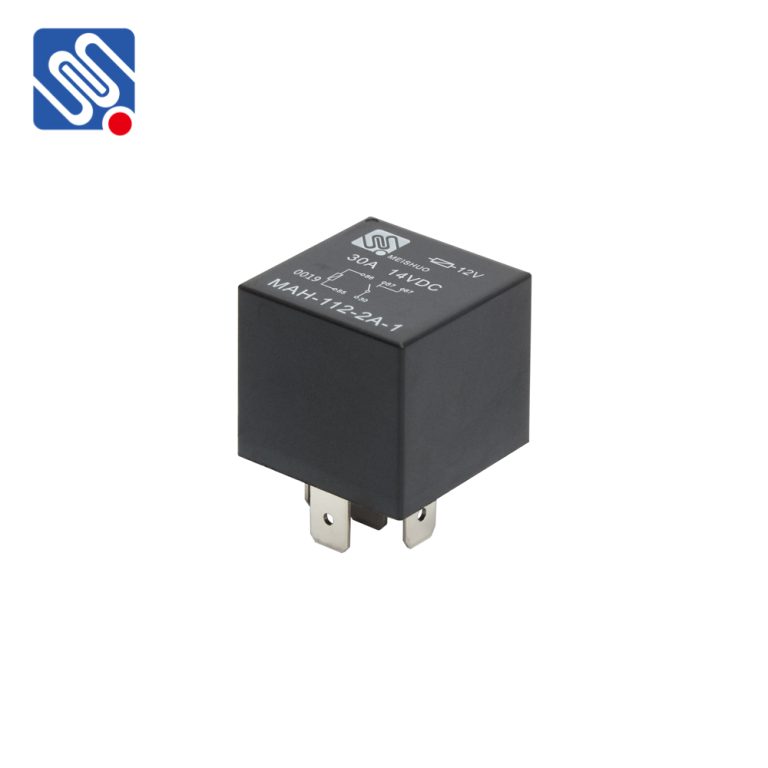
Let’s keep it simple. A 30A relay is an electromechanical switch designed to handle circuits with loads up to 30 amps. It acts as a bridge between a low-power control circuit (like a switch or sensor) and a high-power device (like motors, lights, or heaters). This allows you to safely control large electrical loads without overloading the control circuit.Why is the wiring diagram so important? Because improper wiring can lead to:
1.Equipment failure. 2.Overheating. 3.Short circuits or, worse, fire hazards. So, understanding the wiring diagram is the first step toward a safe and effective installation.Understanding the Bottom View of a Relay
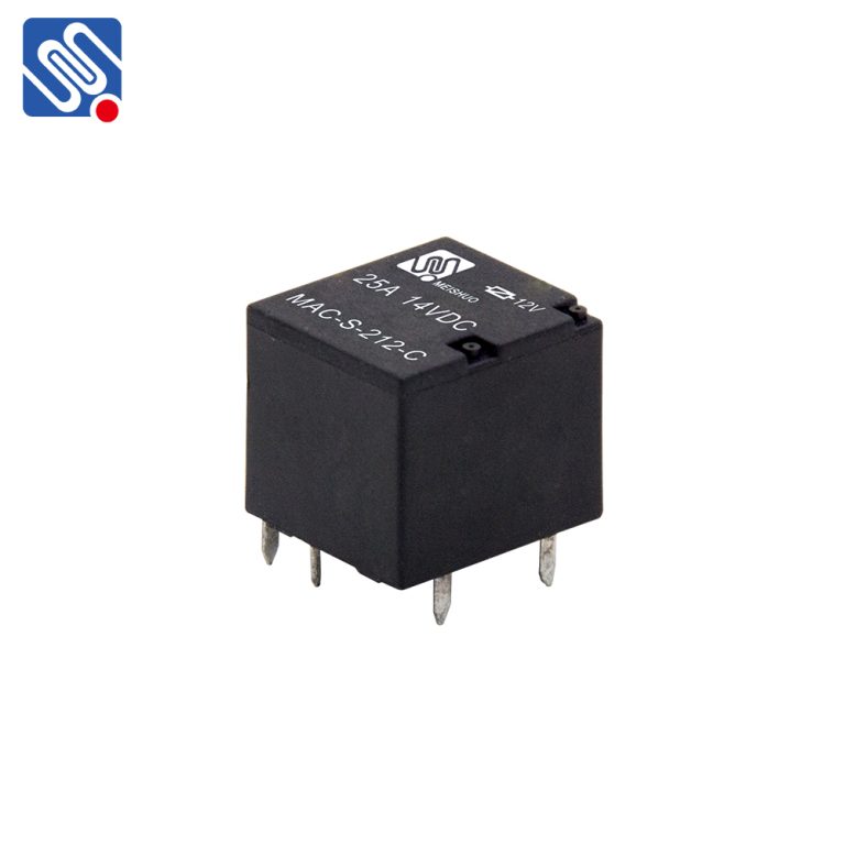
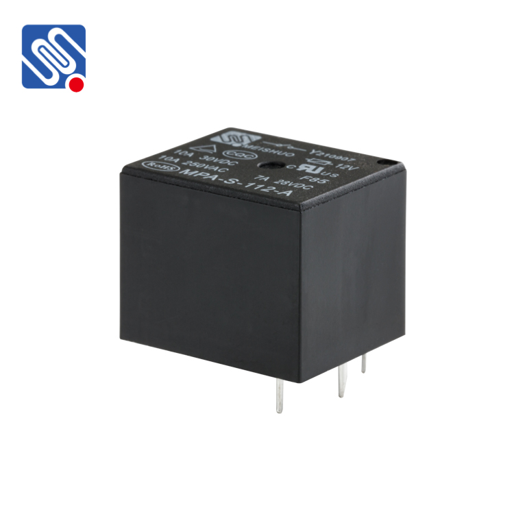
When you flip a relay over, the bottom view shows the connection points for the relay pins. Think of it as a map for wiring everything up. Here’s what you’ll typically find on a 30A relay (bottom view): Pins for the coil: These energise the relay and make it “click” to connect or disconnect the circuit. Common terminal (COM): This is the main input where power or signal comes in. Normally Open (NO) terminal: The circuit is open by default and only closes when the relay is activated. Normally Closed (NC) terminal: The circuit is closed by default and opens when the relay is activated.Decoding a 30A Relay Wiring Diagram
Let’s walk through the process step-by-step. For the sake of this example, let’s say we’re wiring up a 30A relay to control a high-powered light.Step 1: Identify the Relay Pins
First, check the bottom view diagram of the relay (such as the 95224 2D000 diagram) to understand the layout. Most 30A relays have five pins: 85 and 86: Coil terminals. 30: Common terminal. 87: Normally Open terminal. 87a: Normally Closed terminal (not always present in single-throw relays). If the relay is marked with a diagram, you’ll see numbers like this directly on the case.Step 2: Connect the Coil (Pins 85 and 86)
The coil is what activates the relay. Connect: Pin 85 to the negative side (ground). Pin 86 to the positive side (control signal). Tip: You can use a switch, sensor, or control unit to send the signal to Pin 86.Step 3: Connect the Load to Common (Pin 30)
This is where the power flows into the relay. Connect: The power source to Pin 30. For example, if you’re wiring a light, connect the positive terminal of the power supply here.Step 4: Connect the Load to Normally Open (Pin 87)
This is the output terminal. Connect: The load (like a light or motor) to Pin 87. When the relay is activated, the circuit closes, allowing current to flow from Pin 30 to Pin 87.Step 5: Test the Circuit
Once everything is wired, test the circuit: Apply a control signal to the relay (e.g., flip the switch). Check if the load (e.g., light or motor) turns on and off as expected.Common Mistakes to Avoid
When wiring a 30A relay, it’s easy to make small mistakes that lead to big problems. Here’s what to watch out for: 1.Mixing Up the Coil Terminals Always double-check which pins are for the coil (85 and 86). Reversing these won’t usually damage the relay, but the circuit won’t work. 2.Overloading the Relay A 30A relay can handle 30 amps, but consistently pushing it to its limit can cause overheating. Always leave some headroom for safety. 3.Skipping a Fuse Fuses aren’t optional! Install one on the power line to protect against short circuits or overloads. 4.Not Matching the Voltage Ensure the relay coil voltage matches your control circuit (e.g., 12V or 24V). Mismatched voltages can damage the relay or prevent it from working.When Should You Use the Normally Closed (NC) Terminal?
Most applications use the Normally Open (NO) terminal, but the NC terminal can come in handy for devices that need to stay on by default. For example:- Emergency lighting systems.
- Fail-safe circuits that need to turn off during power failures.
Real-Life Example: Wiring a Relay for Car Headlights
Let’s say you’re wiring a 30A relay to control high-powered headlights in a car. Here’s how the wiring looks:- Pin 85: Connect to the vehicle’s ground.
- Pin 86: Connect to the headlight switch (control signal).
- Pin 30: Connect to the battery positive terminal (via a fuse).
- Pin 87: Connect to the headlights.

